Designing and building an open source clock case
Introduction

I got very excited when I saw that this screen came with speakers and in a form factor that would work as a wall clock. I ought to have known how much work this would be as I’d already designed two cases by this point, and yet I still decided to make this happen for some reason
When I first started developing mauveine, I didn’t intend to become a designer of clock cases, but my intention was always that it would become my alarm clock. While there are some commercial Raspberry Pi cases available they all tend to focus on the official display, which at 7” is a little bulky for bedside use.
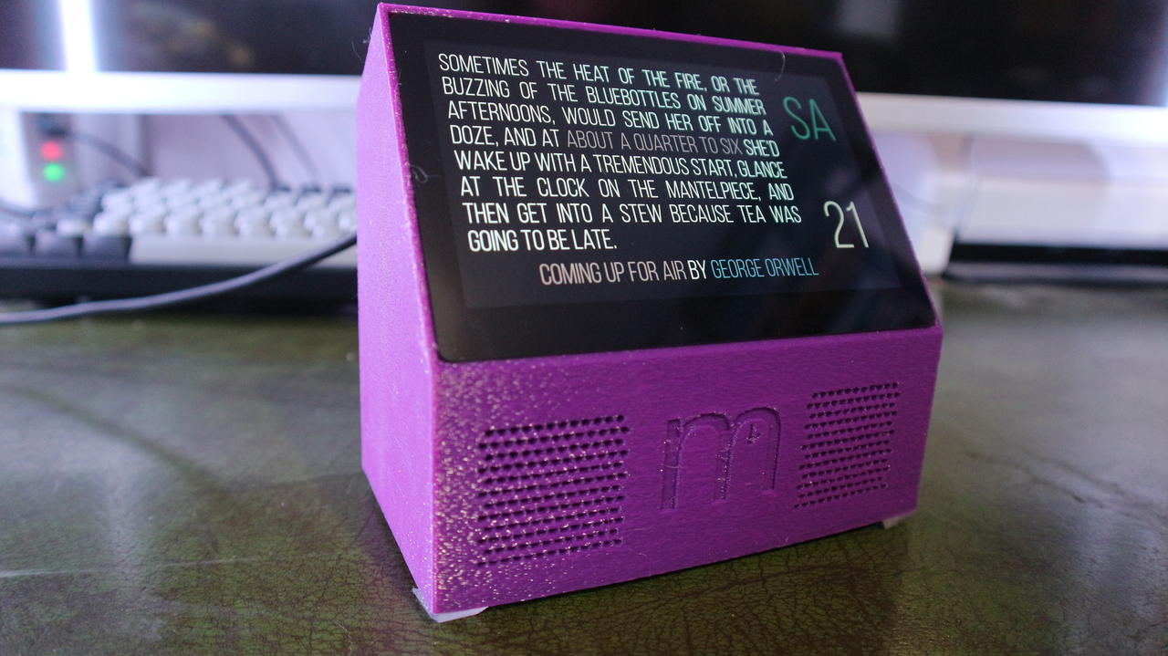
My bedside alarm clock - it only took two years of work to get here
That then sent me down a rabbit hole that, after a truly disproportionate amount of effort has resulted in some quite nice cases for the Raspberry Pi single board computer and its displays. It’s been a road that has been frustrating an interesting in equal measures, so I thought I would document some of the process and some of the questionably useful things I’ve learned dipping my toe into hobbyist hardware design here.
The right tools for the job
Design is not at all my skill set, and I have no experience in computer modelling, but I did have access to 3D printer, a no frills but functional Creality Ender 3. Armed only with a knowledge of basic trigonometry, I decided that rather than try to learn how to do 3D CAD, I was better off using a program like OpenSCAD to create my design. This way I reasoned, it would be easier to adapt it to different screens later.
I think that was a wildly ambitious goal. Each screen has its own quirks and while OpenSCAD will allow you to supply parameters so you can quickly change the dimensions of your model, in practice, this quickly gets sufficiently complex that it’s probably easier to maintain separate CAD files for each type of clock.
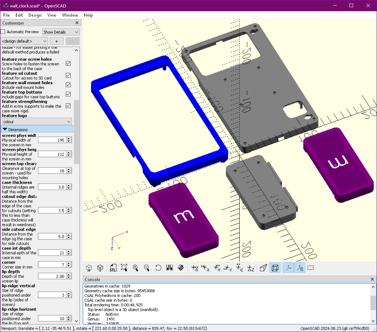
You can see some of the OpenSCAD parameters for the wall clock on the left hand side here. Things get complex fast when you’re trying to remain flexible.
Another thing about OpenSCAD is that its programming language is “opaque” at best. I may have been aware of a tools like PSML to allow you to write your models in python and generate OpenSCAD code, but I felt that adding another layer of complexity into creating models would just make things harder to understand. With hindsight, this was the wrong decision. OpenSCAD has made some courageous choices in the design of its language, particularly around how loops work, which can really catch you out. Writing in python would, I think have been the better choice.
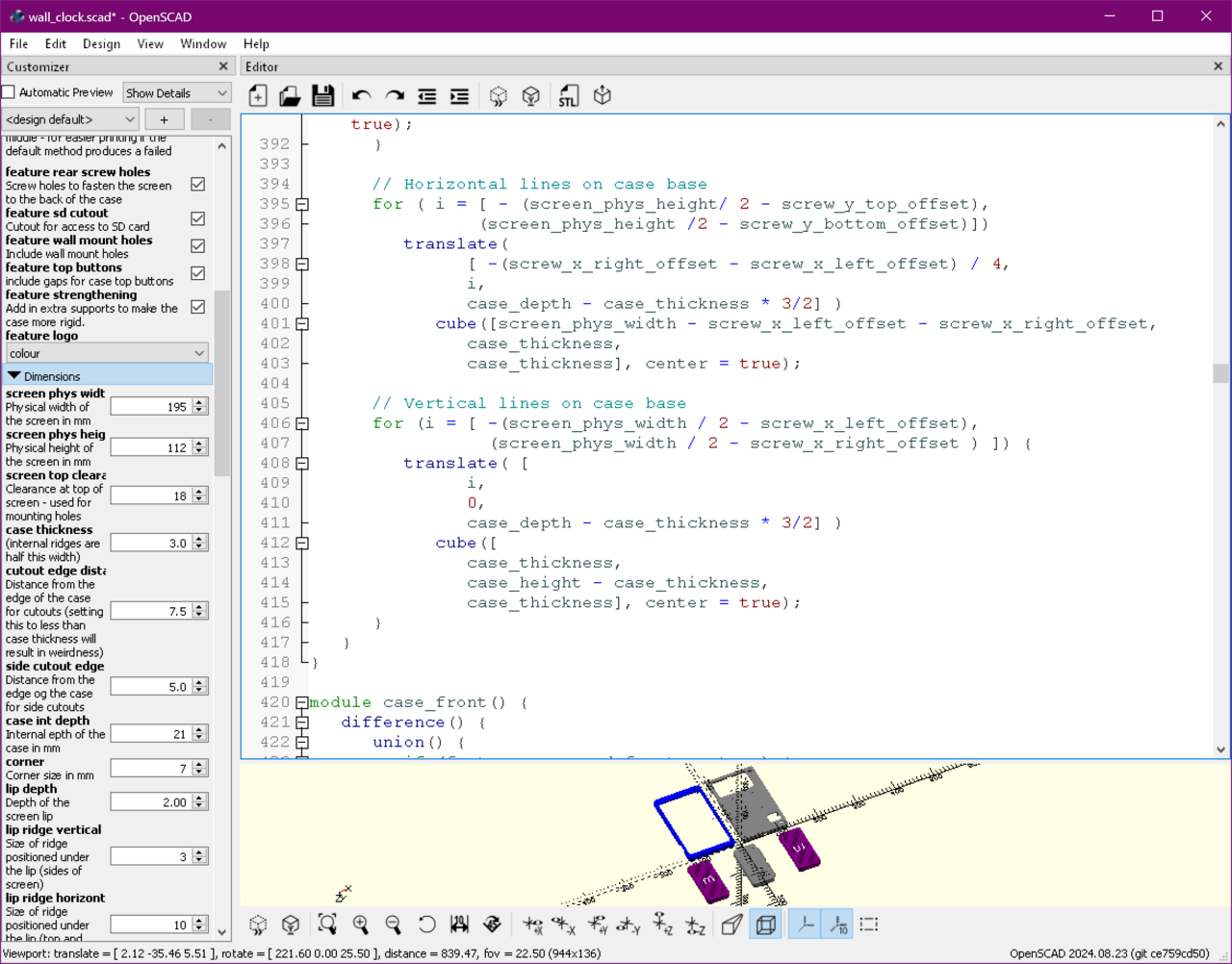
OpenSCAD code can be opaque, and frankly a bit of a maintenance nightmare.
I wonder, if I were starting again, whether I’d want to have a try with FreeCAD instead. Given the lack of gains from parametrisation, this really might have been a better choice.
But for better or for worse OpenSCAD was what I used. On the plus side, it did mean that my second case required only a little extra work after the first one, so some of the parametrisation paid off. The third case, however, involved starting from scratch due to a substantially difficult design.
Learning how not to do things - OpenSCAD
In OpenSCAD everything is built up from a collection of shapes, cubes and spheres etc. You can stick those shapes to others, or you can cut them out of other shapes. Once the shapes get complex, there is a fair amount of mental gymnastics required to work out what is going on. Here are some things I wish I’d understood when I started writing these files.
-
The linear_extrude() function is pretty amazing. It’s often easier to create a shape by “drawing” the bottom of it, then stretching it out in the third direction to produce a solid. Doing the original stand this way would have saved me a lot of time.
-
When designing for 3D printing, you need to consider carefully how to avoid the need for supports. Because 3D printing involves layering thin layers of plastic on top of each other, you need to put extra plastic in to support any objects that would otherwise be printed floating in mid air. You can remove the supports but they leave a rough edge, so generally you want to minimise the need for them.
-
OpenSCAD code can be hard to debug, since a mistake might mean that you are putting a hole in the middle of empty space, and will thus see nothing. The ‘#’ operator will colour the particular item you mark, so you can see where ends up.
-
Use a consistent origin for any objects you create to re-use, otherwise you spend lots of time working out how to position the object correctly. THere are two potentially sane choices - have the (0,0,0) be the centre of the object, or have it be the bottom corner (i.e. no negative points). The former is sometimes slightly more complex when doing positioning, but also sometimes simpler. The latter is initially simpler, but you end up doing the complex calculations in a less transparent way if you are rotating or reflecting the object. For this reason, I’d recommend having your origin in the centre.
-
Parametrisation is powerful, but remember that once you set a parameter, OpenSCAD saves all of your parameters in a config file. This can be confusing if you change one of the other parameters, as it will not update any custom settings to include the new value, even if it was just using the old default. In general, I tended to try to delete any custom parameters created to avoid this.
-
Most real world objects don’t have sharp corners. Unless you round off your corners in at least one dimension, they will feel weird.
-
Technical specifications lie - check measurements where you can. A set of digital calipers makes this work a lot better, but sadly still not trivial.
-
OpenSCAD is a functional language. This means variables, well, aren’t. Once a value is set, it can’t be changed. In most circumstances this doesn’t matter but it make some things (iteration in particular) quite hard. It requires a style of coding that is quite alien to me, but not to an unmanageable degree.
Learning how not to do things - 3D printing
Needless to say I was a complete novice when it came to 3d printing before the start of this project. These skills did not come naturally to me, and as a software person, it always felt very frustrating for failures to be permanent and have a turnaround time in hours. Again, here’s some things I’ve learned about the printing process.
-
Materials matter. I found that some printing materials needed additional tolerances to make things fit right, but some did not. I was eventually able to get good results with both PETG and PLA.
-
Hairspray on the build plate is an excellent way to prevent large prints lifting off the base of the printer.
-
A good printer really matters. The Creality Ender 3 in use initially was OK, but extremely temperamental as it did not have any automatic bed levelling. I generally found it too frustrating to use, and had to rely on help to get my prints to print at all. Moving to a Bambu Labs A1 meant the project moved to practical level. The A1 took most of the frustration out of printing, and allowed me to do cool things like multi-colour prints. I don’t think I would have got through it without the A1.
Sadly Bambu Labs have started to lock things down in their firmware of late, and it’s difficult to recommend getting one at the moment until it’s clearer they aren’t going to push their users into a closed ecosystem.
-
Filament needs to be kept dry. Airtight vacuum bags and desiccant or a filament drier are essential if you don’t want a lot of failed prints.
-
Similarly, always wash the build plate with water and detergent between prints. It saves time in the long run. Some new plates are coming onto the market that say they don’t need this, which will be nice, if that’s right.
-
Multi-colour is best used sparingly, and uses a lot of filament plus increases printing time considerably. It’s best to confine multicolour elements to a small number of layers.
Some smaller Pi screens came with a case built in. The problem with those, is that they generally laid flat on the desk, and you want to be able to control an alarm clock from above. The first case design I therefore came up with was effectively a stand that the Pi case could rest on.